簡(jiǎn)單的直流電機(jī)PWM調(diào)速電路

簡(jiǎn)單的直流電機(jī)PWM調(diào)速電路 Simple DC motor PWM speed control
本文引用地址:http://www.ex-cimer.com/article/163260.htmThe 555 is ubiquitous and can be used as simple PWM speed control
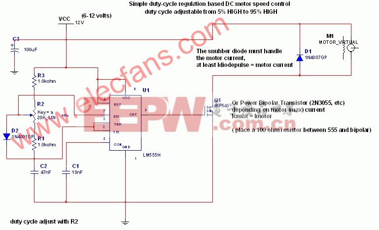
Circuit Explaination:
The 555 Ic is wired as an astable and the frequency is constant and independent of the duty cycle, as the total resistance (R charge + R discharge, notice the diode) is constant and equal to 22Kohm (givin a frequency of about 1Khz, notice the hum).
When the potentiomenter is all up, the Rcharge resistance is 1,0 Kohm (the diode prevents the capacitor to charge through the second potentiometer section and the other 1,0 Kohm resistor) , and Rdischarge is 21 Kohm, giving a 5% on duty cycle and a 1Khz frequency.
When the potentiomenter is all down, the Rcharge resistance is 21,0 Kohm (the diode prevents the capacitor to charge through the second potentiometer section and the other 1,0 Kohm resistor) , and Rdischarge is 1 Kohm, giving a 95% on duty cycle and a 1Khz frequency.
When the potentiomenter is at 50% , the Rcharge resistance is 11,0 Kohm (the diode prevents the capacitor to charge through the second potentiometer section and the other 1,0 Kohm resistor) , and Rdischarge is 11 Kohm, giving a 50% on duty cycle and a 1Khz frequency.
The 555 provide good current capability to drive the mosfet fast and to drive a bipolar transistor.
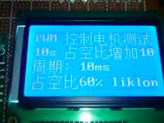
I actually use this system to drive the DC motor of my small Rotary spark gap Tesla coil at variable speed
If you are disgusted by the 1Khz hum of the motor try to rise the frequency out of the audible range (replacing the potenziometer), but rembember that at higher frequency inductive reactance of motor rises so the the efficiency would drop.
Important:
Obviously the mosfet (or bipolar) must have enough current capability to drive the motor, so the drain (or collector) current must be equal to maximum motor current (at power supply voltage, when it is blocked). The snubber diode too, because it shorts the motor on the off cycle. Both mosfet (or bipolar) and diode have to be hooked (if you don't want them cooked ;-) ) to a heatsink
if the max motor current is more than 100 or 200mA. I suggest to not stress to much the motor with too much work because it overheats both motor, transistor and diode.
If you don't want braking in the off cycle just place a resistor in series with the snubber diode, it should rise a bit efficiency but have more inertia when slowing the motor down. The value of the resistor must be R=V(breakdown transistor) / Imax, and the power should be 5W. Mosfets have internal zener diode, but don't count on it ;-)

DIY機(jī)械鍵盤相關(guān)社區(qū):機(jī)械鍵盤DIY
電路相關(guān)文章:電路分析基礎(chǔ)
pwm相關(guān)文章:pwm是什么
pwm相關(guān)文章:pwm原理


評(píng)論