基于MIC3203設(shè)計的HBLED驅(qū)動方案
圖2.MIC3203降壓LED驅(qū)動器電路
MIC3203/MIC3203-1 評估板
This board enables the evaluation of the MIC3203/MIC3203-1 for 1A LED current. The board is optimized for ease of testing, with all the components on a single side. The device operates from a 4.5V to 42V input voltage range, and controls an external power MOSFET to drive high current LEDs. When the input voltage approaches and crosses UVLO threshold, the internal 5V VCC is regulated and the integrated MOSFET is turned on if EN pin and DIM pin are high.
The inductor current builds up linearly. When the CS pin voltage hits the VCS(MAX) with respect to VIN, the external MOSFET is turned off and the Schottky diode takes over and returns the current to VIN. Then the current through inductor and LEDs starts decreasing. When CS pin hits VCS(MIN), the external MOSFET is turned on and the cycle repeats.Since the control scheme does not need loop compensation, it makes for a very simple design and avoids problems of instability.
Requirements
This board needs a single bench power source adjustable over the input voltage of 4.5V VIN 42V that can provide at least 1A of current. The loads can either be active (electronic load) or passive (LEDs) with the ability to dissipate the maximum load power while keeping accessible surfaces ideally 70℃.

圖3.MIC3203/MIC3203-1 評估板電路圖
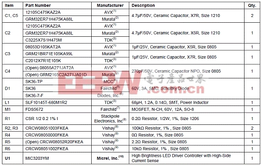
MIC3203/MIC3203-1評估板材料清單(BOM):
 本文引用地址:http://www.ex-cimer.com/article/180747.htm



評論