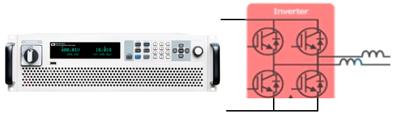
基于EconoDUAL 3設(shè)計的600A/1200V汽車驅(qū)動方案

The new EconoDUAL 3 module with the designation FF600R12ME4 is at present the most powerful product in the popular EconoDUAL family, offering 600A in 1200V. Typical applications are frequency converters in automation drive systems, central inverters in photovoltaic systems, and diesel generator drives in vehicles (CAV). The optimised module design with regard to interconnection technology and thermal resistance, results in high current utilisation and thus high efficiency. With the EconoDUAL 3 FF600R12ME4, the user can increase the power range by up to 30%, while the package dimensions remain the same. In addition to the familiar soldered version of the control contacts, the highly reliable PressFIT contact technology has been introduced in the EconoDUAL 3 family.
The FF600R12ME4 is the new flagship product of Infineon’s well established EconoDUAL series. It was developed with a clear focus on full current and power utilization within the inverter design. Hence, the ampacity of the package was increased by ~50% and the thermal resistivity R thJC was reduced by ~25%, compared to state-of-the-art assembly technologies.
Based on the previous considerations, the development of a new EconoDUAL 3 module has been started. The development target was not only to achieve a nominal current rating of 600A in the 1200V blocking voltage class by the implementation of the latest IGBT 4th generation dies, but also to provide a real increase of the achievable RMS output current of the inverter, compared to the already existing 450A EconoDUAL 3.

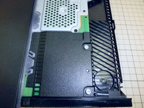
圖1.1200V/600A EconoDUAL3模塊外形圖
Newly developed 1200V EconoDUAL 3 with 600A nominal current, utilizing copper bond wires and optimized DBC.
The FF600R12ME4 is the new flagship product of Infineon’s well established EconoDUAL series. It was developed with a clear focus on full current and power utilization within the inverter design. Hence, the ampacity of the package was increased by ~50% and the thermal resistivity R thJC was reduced by ~25%, compared to state-of-the-art assembly technologies.
The new FF600R12ME4 does not only aim for new inverter developments: Offering the possibility of up to 30% more output power in the popular EconoDUAL package includes the advantage to upgrade existing inverter designs without changing the mechanical set-up as well, making such an approach a fast, cheap and therefore very attractive solution.
FF600R12ME4目標應(yīng)用:
Main target applications of the FF600R12ME4 are:
General purpose drives
CAV
Central solar inverters
Power supplies
And further more
EconoDUAL3 和EconoPACK+模塊驅(qū)動板
Evaluation Driver Board for EconoDUAL3 and EconoPACK+ modules
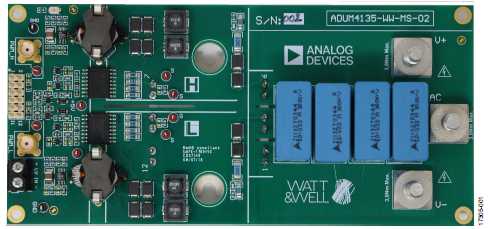
The Evaluation Driver Board 2ED100E12-F2 for EconoDUAL3 modules as can be seen in Figure 1 and the Evaluation Driver Board 6ED100E12-F2 for EconoPACK+ modules, shown in Figure 2, were developed to support customers during their first steps designing applications with these modules. The basic version of each board is available from Infineon in small quantities. The properties of these parts are described in the chapter 2.2 of this document whereas the remaining paragraphs provide information intended to enable the customer to copy, modify and qualify the design for production, according to his specific requirements.
The design of the 2ED100E12-F2 and the 6ED100E12-F2 was performed with respect to the environmental conditions described as design target in this document. The requirements for leadfree reflow soldering have been considered when components were selected. The design was tested as described in this documentation but not qualified regarding manufacturing and operation in the whole operating ambient temperature range or lifetime.
Due to their purpose Evaluation Boards are not subjected to the same procedures regarding Returned Material Analysis (RMA), Process Change Notification (PCN) and Product Discontinuation (PD) as regular products.
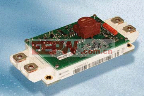
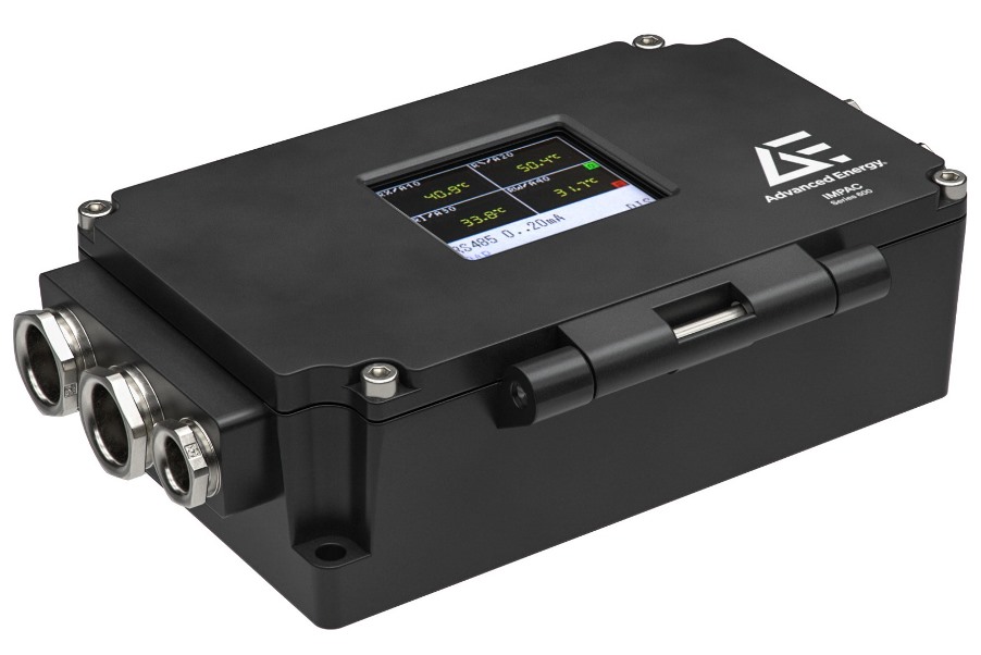
圖2.EconoDUAL3模塊驅(qū)動板外形圖
EconoDUAL3模塊驅(qū)動板主要特性:
The 2ED100E12-F2 and the 6ED100E12-F2 Evaluation Driver Board offers the following features:
Dual channel IGBT driver in 2ED100E12-F2 version, adapted for use with IGBT4
Six channel IGBT driver in 6ED100E12-F2 version
Electrically and mechanically suitable for 600 V and 1200 V EconoDUAL3 or EconoPACK+ IGBT modules
Includes DC/DC power supply with short circuit protection
Isolated temperature measurement
Short circuit protection with toff 6 μs
Under Voltage Lockout of IGBT driver IC
Positive logic with 5 V CMOS level for PWM and Fault signals
One fault output signal for each leg
PCB is designed to fulfil the requirements of IEC61800-5-1, pollution degree 2, overvoltage category III
The 2ED100E12-F2 and the 6ED100E12-F2 have an integrated DC/DC converter for each leg, which generates the required secondary isolated unsymmetrical supply voltage of +16 V / -8 V. Top and Bottom driver voltages are independently generated by using one unipolar input voltage of 15 V. Additionally, the power supply is protected against gate C emitter short circuit of the IGBTs. In case of DC/DC converter overload, the output voltage drops. This Under Voltage Detection function insures gate voltages within specified range. The fault is reported to the driver’s primary side.
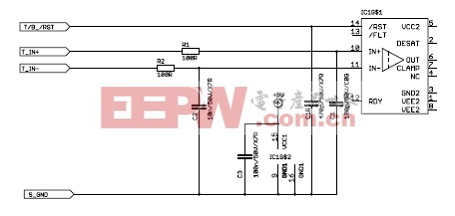
圖3.單個驅(qū)動器輸入電路圖
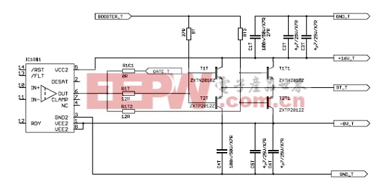
圖3.升壓器電路圖

圖4.去飽和保護和有源鉗位二極管電路圖
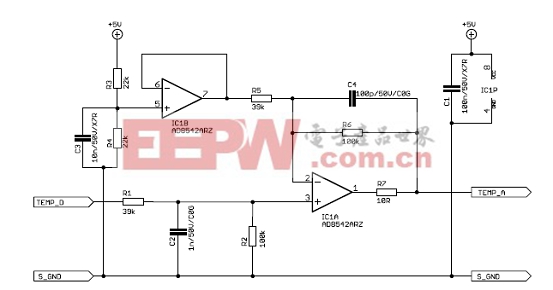
圖5. 數(shù)字Σ/Δ轉(zhuǎn)換成模擬輸出電路圖
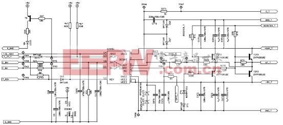
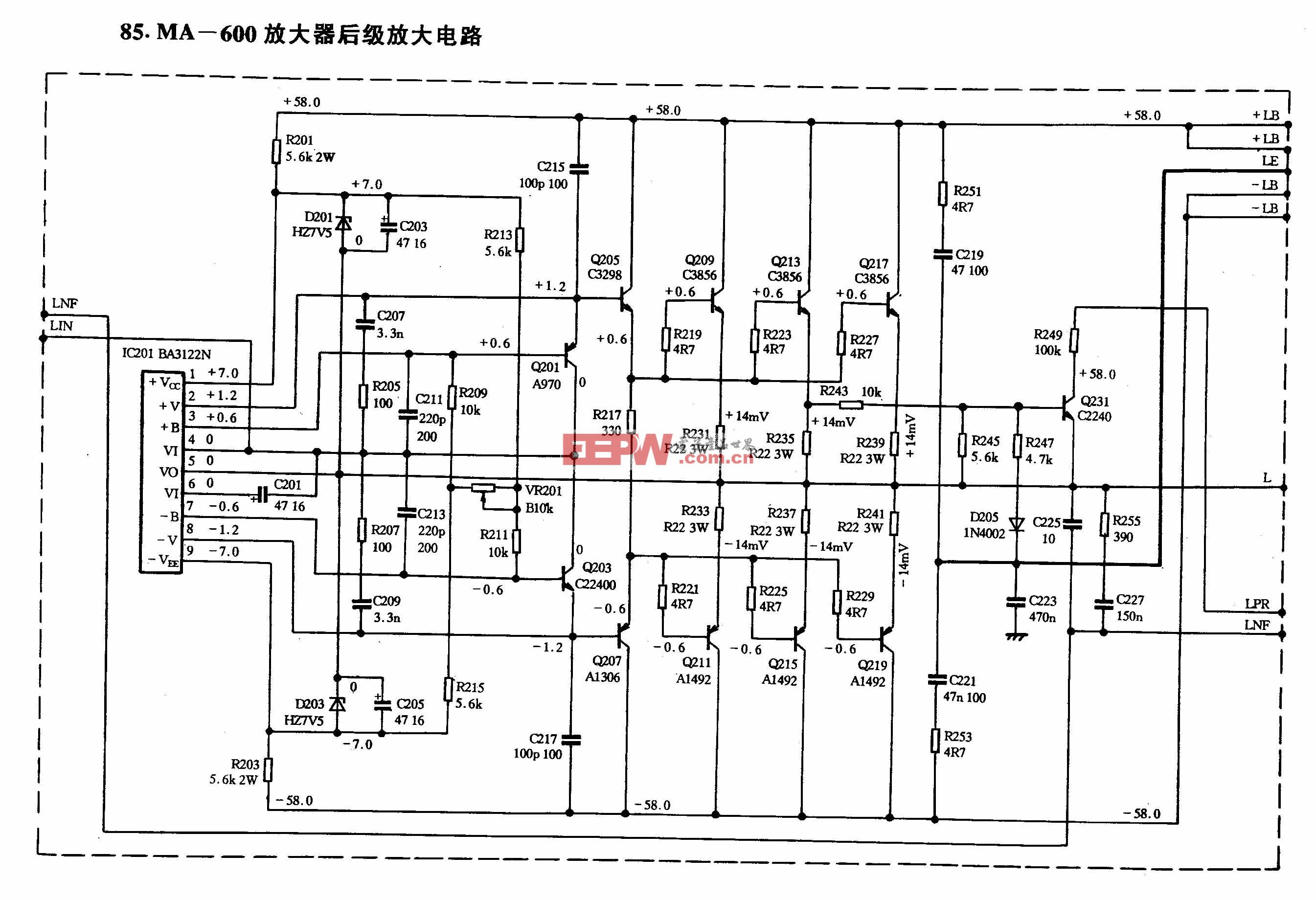
圖6. IGBT驅(qū)動器-頂部晶體管


評論