交點(diǎn)分析運(yùn)算放大器電路-Nodal Analysis of

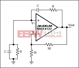
Figure 3.
Firstly, from Equation 3 the voltage at the inverting pin is
It is worth noting that if two admittances are placed in series, the total admittance is the inverse of the sum of their reciprocals (using the same formula as for two resistors in parallel). Similarly if two admittances are placed in parallel, the total admittance is sum of the admittances. Therefore the admittance from the output of the op amp to the non inverting input is
Likewise the admittance from the non inverting terminal to ground is
Using the methodology from before, it can be shown that (eventually)
Putting s = jw and R = 1/G gives
Therefore, using the principles of nodal analysis, the transfer function for the Wien bridge oscillator has been derived. From this equation two conclusions can be drawn, both of which are well known conditions for oscillation of the Wien bridge oscillator.
First, for oscillation to occur, there must be zero phase shift from the input to the output. This only happens at one frequency (when w = 1/CR). At this frequency the real terms of the numerator cancel and the phase shift represented by the imaginary terms in both numerator and denominator cancel (essentially, if you have no j terms in either numerator or denominator, there is no phase shift). Second, at this frequency the ratio of VOUT to V+ (hence V-) has to be 3. Anything less than 3 and the oscillation will decay. Anything greater than 3 and the output will saturate. This dictates the ratio of Gf to Gi to maintain oscillation: Rf must be equal to precisely twice the value of Ri.
Conclusion
Using Kirchoff's law, the currents flowing into and out of the nodes around the op amp can be translated into equations and from this the transfer function can be derived. The above examples use admittances instead of impedances, but the principles are the same and it is left to the engineer to decide which is more suitable. Once the equations have been derived, the math (depending on the complexity of the circuit) is moderately straightforward to obtain the transfer function. Then the power of math processing programs can be unleashed on the equations to find when, for example, instability occurs, or the susceptibility of the circuit to component variations, if this is desired.A similar version of this article appeared in the December 2002 issue of New Electronics magazine.
電流傳感器相關(guān)文章:電流傳感器原理


評(píng)論