12-Bit Thermometer Using an 8-

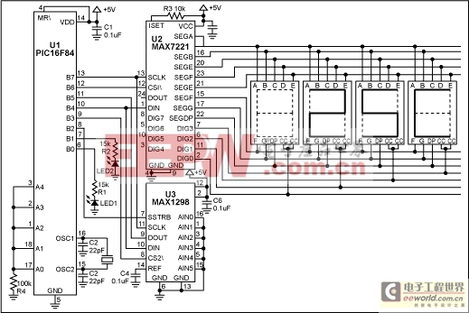
Figure 1. With an assembly-language routine and the free assembler, this circuit allows an 8-bit μC to implement a 12-bit digital thermometer.
U1 is a low-cost, 8-bit flash μC with only 35 instructions. Unlike more expensive, multiply-friendly 16-bit μCs, this one has no multiply, divide, or even 16-bit math instructions. The result is a more challenging implementation of the thermometer! The μC (U1) receives a serial data word (Kcode) from the temperature sensor (U3). Using the following equations, it then converts Kcode to a binary representation of the temperature in degrees Celsius:
K = Kcode x 0.125, where K = temperature in degrees Kelvin.
°C = K - 273, where °C = degrees Celsius.
Table 1 shows the data as it appears after each of five steps in the conversion process, using the decimal-equivalent number 2384 as an example for Kcode. The first step reads both halves of the Kcode value from U3 (high byte and low byte), and stores that data in separate 8-bit file registers. The second step aligns the Kcode data by rotating the bits in both 8-bit file registers two places to the right, checking the carry flag each time to properly shift the LSB of the high byte to the MSB of the low byte. The third step multiplies Kcode by 0.125. Multiplying by 0.125 is a bit complicated, but the equivalent operation of division by 8 is much easier. Because 8 is the third power of 2, division by 8 can be accomplished (with our limited instruction set) by three consecutive right shifts.
To convert to degrees Celsius, the fourth step subtracts 273 from the Kelvin temperature K. Eight-bit arithmetic, however, supports integers only to 255. Because 273 exceeds the 8-bit boundary, a code routine for 16-bit subtraction was used to produce a binary representation of the temperature in degrees Celsius.
To take full advantage of the BCD register map internal to U2, the last (fifth) step converts the binary representation of temperature in degrees Celsius to the BCD data format. A 16-bit routine for binary-to-BCD conversion allows temperature to be displayed using the LED display driver U2.
An assembly-language program for the μC is can be downloaded from the Maxim website.
Table 1. Five steps allow an 8-bit μC to support 12-bit temperature data and display it.
μC's 8-bit File Register #1 (high byte) | μC's 8-bit File Register #2 (low byte) | ||||||||||||||
| Step 1: The Kcode value is serially read out of U3. For example, Kcode = 2,384 decimal below. | |||||||||||||||
X | X | MSB D12 | D11 | D10 | D9 | D8 | D7 | D6 | D5 | D4 | D3 | D2 | LSB D1 | 0 | 0 |
X | X | 1 | 0 | 0 | 1 | 0 | 1 | 0 | 1 | 0 | 0 | 0 | 0 | 0 | 0 |
| Step 2: The Kcode is byte aligned. Kcode is still equal to 2,384 decimal below. | |||||||||||||||
0 | 0 | 0 | 0 | MSB D12 | D11 | D10 | D9 | D8 | D7 | D6 | D5 | D4 | D3 | D2 | LSB D1 |
0 | 0 | 0 | 0 | 1 | 0 | 0 | 1 | 0 | 1 | 0 | 1 | 0 | 0 | 0 | 0 |
| Step 3: Shifting the data right three places is equivalent to multiplying by 0.125 to obtain the Kelvin temperature. For example, K = 298 below. | |||||||||||||||
0 | 0 | 0 | 0 | MSB D12 | D11 | D10 | D9 | D8 | D7 | D6 | D5 | D4 | D3 | D2 | LSB D1 |
0 | 0 | 0 | 0 | 0 | 0 | 0 | 1 | 0 | 0 | 1 | 0 | 1 | 0 | 1 | 0 |
| Step 4: A 16-bit subtraction code routine must be used to subtract 273 from K, because 273 exceeds 8 bits. For example, °C = 25 below. | |||||||||||||||
See code listing for the 16-bit subtraction code routine. | D8 | D7 | D6 | D5 | D4 | D3 | D2 | LSB D1 | |||||||
0 | 0 | 0 | 1 | 1 | 0 | 0 | 1 | ||||||||
| Step 5: A 16-bit binary-to-BCD conversion routine must be used because that is the format used by the LED display driver. For example, 25C below. See code listing for the 16-bit binary to BCD conversion code routine. | |||||||||||||||
LED 0 | LED 1 | LED 2 | LED 3 | ||||||||||||
CURRENTLY BLANK | D8 | D4 | D2 | D1 | D8 | D4 | D2 | D1 | Permanent "C" is displayed to represent " °C " | ||||||
CAN BE NEGATIVE SIGN | 0 | 0 | 1 | 0 | 0 | 1 | |||||||||


評論