理想性因數(shù)補(bǔ)償和串聯(lián)電阻差異熱感二極管-Com

The most common approach to measuring temperature with a "remote diode" temperature sensor is to force two different currents through the diode1, typically with a current ratio of about 10:1. The diode's voltage is measured at each current level and the temperature is calculated based on the equation,
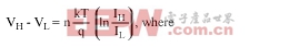
IH is the larger diode bias current
IL is the smaller diode bias current
VH is the diode voltage while IH is flowing
VL is the diode voltage while IL is flowing
n is the ideality factor of the diode (nominally 1, but varies with processing)
k is Boltzmann's constant (1.38x10⁻²³joules/K)
T is the temperature in K
q is the charge of an electron (1.60x10⁻¹⁹C)
If
 = 10, this can be simplified t
Ideality Factor Correction
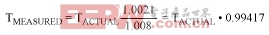
Note that the accuracy of the temperature reading depends on the value of n. If the remote diode sensor is designed to produce correct readings with a diode that has a specific value of n, changing to a diode with a different ideality factor will change the apparent measured temperature.Correcting for differences in ideality factor is done as follows: Assume a remote diode sensor designed for a nominal ideality factor nNOMINAL is used to measure the temperature of a diode with a different ideality factor nACTUAL. The measured temperature TMEASURED can be corrected using,

where T is the temperature in °K.
Most remote diode temperature sensors for CPUs are designed to produce accurate temperature data when used with an ideality factor of 1.008. Some newer CPU thermal sense diodes have lower ideality factors. To use a CPU optimized for an ideality factor of 1.008 with a CPU that has an ideality factor of 1.0021, the data can be corrected (assuming no series resistance) as follows:
For an actual temperature of 85°C (358.15°K), the measured temperature will be 82.91°C (356.06°K), an error of -2.09°. Note that the error is proportional to absolute temperature. At 125°C, the error increases to -2.32°.
Series Resistance Correction
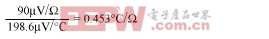
Series resistance in one of the diodes contributes additional errors. For the nominal diode currents of 10μA and 100μA used in Maxim's remote temperature sensors, the change in the measured voltage will be,
Since 1°C corresponds to 198.6μV, series resistance contributes a temperature offset of
Assume that the diode being measured has a series resistance of 3.86Ω. The series resistance contributes an offset of

If the diode has an ideality factor of 1.0021 and series resistance of 3.86Ω, the total offset can be calculated as follows. Combining the correction for series resistance with the correction for ideality factor, we have
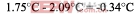
for a diode temperature of 85°C. Thus, in this case the effect of the series resistance and the ideality factor partially cancel each other.
Note that if the diode bias current is different, the effect of series resistance will change proportionally. For example, some remote temperature sensors have diode bias currents two or more times larger than those of Maxim's remote sensors. The resulting temperature errors can be on the order of two or more degrees larger than those observed with Maxim's sensors.
1This diode is not a two-lead rectifier or signal diode like a 1N4001. Such diodes will not work with remote-diode temperature sensors. Instead, the diode is really a bipolar transistor connected as a diode. If the transistor is a discrete unit, its base and collector should be connected together. If the transistor is a substrate PNP, the collector will be grounded and the base and emitter serve as the cathode and anode. When "diode" is used in this document, it refers to the diode-connected transistors described above.


評(píng)論