升壓控制器形式負(fù)降壓穩(wěn)壓-Step-Up Controlle

Figure 1 shows a negative step-down switching regulator that delivers 1A at -7.5V from -15V, with efficiency better than 90%. The IC is a step-up switching controller referenced to the negative rail.
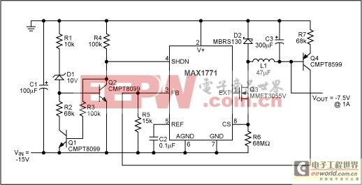
Figure 1. This negative step-down circuit regulates -15V down to -7.5V.
When the power switch (Q3) turns on, the current in L1 increases as long as VOUT is less negative than VIN. When this inductor current reaches the limit set by R6, Q3 turns off. Q3's drain flies high and is clamped to the positive supply rail (ground) by the catch diode (D2). Inductor current then decreases until Q3 turns on again. The output capacitor (C3) integrates inductor current to produce the output voltage.
Output voltage is referenced to the positive supply rail, and Q4 reflects the error signal from the positive rail to the negative rail. When the error signal falls below the feedback threshold, the power switch turns on and initiates another switching cycle.
D1, Q1, Q2, and R1-R4 form a startup circuit that holds IC1 in shutdown until VIN reaches approximately -11V. This action ensures that Q4 has sufficient voltage compliance to regulate the feedback loop. The minimum input voltage necessary to maintain a regulated output voltage is VOUT +(-VFB), where VFB is the feedback threshold voltage (1.5V in this case). Efficiency varies with load current as shown in Figure 2.
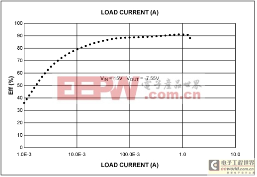
Figure 2. Conversion efficiency for the Figure 1 circuit rises with load current.
The MAX1771 controller IC used in this circuit operates in the pulse-frequency modulation (PFM) mode. The MAX668 controller IC, which operates in the pulse-width modulation (PWM) mode, could be used in a similar circuit to step-down a negative voltage. PWM controllers offer the advantage of fixed-frequency operation. The MAX668 controller offers the further advantage of coming in a smaller package than the MAX1771 PFM controller.
A similar version of this article appeared in the September 6, 1999 issue of EE Times magazine.


評(píng)論