常用詞匯的高速數(shù)據(jù)轉(zhuǎn)換器條款-Glossary of Fre

Aliasing/Anti-Aliasing
In sampling theory, an input signal (fIN) must be sampled with at least twice its frequency (Nyquist criteria, fSAMPLE ≥ 2 × fIN). If the input tone exceeds the Nyquist limit, the signal is folded back (aliasing) or replicated at other frequencies in the frequency spectrum above and below Nyquist (see also Nyquist Frequency). Caused by unwanted signal components above Nyquist, aliasing can be avoided by introducing front-end anti-aliasing filters to attenuate those signals.Aperture Delay
Aperture delay is the time defined between the rising edge (50% point) of the sampling clock and the instant when an actual sample is taken.Aperture Jitter
Aperture jitter is the sample-to-sample variation in the time between sampling events.Aperture Width
Aperture width is the time that a track/hold (T/H) circuit requires to disconnect the hold capacitor from the input circuit (for example, to turn off the sampling bridge and put the T/H unit in hold mode).Best-Straight-Line INL
Best-straight-line INL (integral nonlinearity) provides information about offset and gain error, plus the position of the transfer function. It determines, in the form of a straight line, the closest approximation to the data converter's actual transfer function. The exact position of the line is not clearly defined, but this approach yields the best repeatability, and it serves as a true representation of linearity.Channel-to-Channel Crosstalk
For an ADC with more than one input channel, channel-to-channel crosstalk is the amount of signal interference (in dB) from one analog input channel to any of the other input channels. For a DAC, channel-to-channel crosstalk is the amount of noise appearing on a DAC output when another DAC is being updated.Coherent Sampling
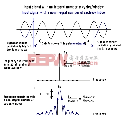
Sampling of a periodic waveform such that there is an integer number of waveform cycles in the data record. Coherent sampling (see also Incoherent Sampling and Spectral Leakage) occurs according to the following relationship:fSAMPLE × NWINDOW = fIN × NRECORD, wherefSAMPLE = Sampling frequency
fIN = Reciprocal of the period of the input-tone waveform
NWINDOW = Integer number of cycles of the waveform in the data record
NRECORD = Number of samples/data points in the data record
Common-Mode Input Voltage (VCM)
VCM is the average value of the input signals at the positive input and the negative input of a differential-input ADC. With the positive input expressed by VIN+ and the negative input expressed by VIN-, VCM is computed as follows:VCM = (VIN+ + VIN-) / 2
Differential Input Signal (VDIFF)
VDIFF is the difference (VDIFF = VIN+ - VIN-) between the signal at the positive (VIN+) and negative (VIN-) inputs of a differential-input ADC.Differential Nonlinearity (DNL)
DNL error is defined as the difference between an actual step width and the ideal value of one LSB. For an ideal data converter, in which the differential nonlinearity coincides with DNL = 0LSB, each analog step equals 1LSB (1LSB = VFS/2N, where VFS is the full-scale range and N is the resolution of the converter) and the transition values are spaced exactly 1LSB apart. A DNL error of less than or equal to -1LSB indicates missing codes in the transfer function. The DNL graph for a DAC displays the digital input code on the X-axis and the analog output (voltage or current) on the Y-axis.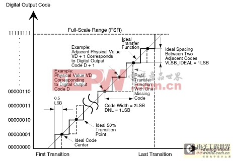
Digital Feedthrough
This is the amount of noise/interference that appears on a DAC output caused by coupled frequency components from either DAC inputs or DAC clock. Digital feedthrough increases distortion, thereby reducing the DAC's dynamic range (see also Dynamic Range and Spurious-Free Dynamic Range).Dithering
Dithering is a common technique to improve digitizing when quantization noise (see also Quantization Error/Noise) can no longer be treated as random. This happens when an analog input signal remains at the same value for many consecutive samples, causing the digitized output to look "stuck" at a certain digital output code even when the input is changing by less than ±0.5LSB. The quantization noise now looks more like a threshold or a distortion rather than additive random noise. To get around this effect, a small amount of random noise is added to the analog input signal. This added noise causes the digital output to randomly toggle between two adjacent codes, thereby avoiding the previously described thresholding effect.DNL
See Differential Nonlinearity (DNL).Dynamic Range
The dynamic range of a data converter (ADC and DAC) is the range of signal amplitudes it can process effectively. The minimum signal usually is the point where parameters such as SNR are 0dB (for example, signal power equals noise power) and the maximum signal is either the data converter's full-scale input or the point where distortions become an unacceptable large factor.Effective Number of Bits (ENOB)
ENOB specifies the dynamic performance of an ADC at a specific input frequency, amplitude and sampling rate releative to an ideal ADC's quantization noise. ENOB is computed from: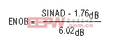
Endpoint INL
Endpoint INL (integral nonlinearity) passes the straight line through endpoints of the converter's transfer function, thereby defining a precise position for the line. This straight line is defined by the zero- and full-scale outputs of the data converter.ENOB
See Effective Number of Bits (ENOB).Flash Architecture
A flash converter with N-bit resolution has 2N-1 comparators connected in parallel, with reference voltages set by a resistor network, and spaced VFS/2N (1LSB) apart. The outputs of the comparators are combined in a decoder-logic unit that produces a parallel N-bit output from the converter.FPBW
See Full-Power Input Bandwidth (FPBW).Frequency Bin
The frequency range and resolution on the frequency axis of a spectrum (FFT) graph usually depend on the sampling rate and the size of the data record (the number of acquisition points). The number of frequency points or lines in the power spectrum is NRECORD/2, where NRECORD is the number of signal points captured in the time domain. The first frequency line in the power spectrum always represents DC. The last frequency line can be found at fSAMPLE/2 - fSAMPLE/NRECORD. Frequency lines are spaced at even intervals of fSAMPLE/NRECORD, commonly referred to as frequency or FFT bins. Bins can also be computed with reference to a data converter's sampling period:Bin = fSAMPLE/NRECORD = 1/(NRECORD × ΔtSAMPLE)
Full-Power Input Bandwidth (FPBW)
A large analog input signal (for example, -0.5dB FS) is applied to an ADC, and the input frequency is swept up to the point where the amplitude of the digitized conversion result has decreased by -3dB. This point is defined as full-power input bandwidth frequency.Full-Scale (FS) Input Range
A full-scale (FS) input range is the difference between the maximum and the minimum recordable input values, as specified by the manufacturer, when the specified reference values are applied to the data-converter reference inputs.Full-Scale (FS) Input Signal
A full-scale input signal is a signal whose peak-to-peak amplitude spans the entire range of input values recordable by a data converter.Glitch Energy
A glitch is generated when, during a major carry code transition (see also Major Code Transition), the new code signal value appears before or after the signal value of the previous code disappears. Typically measured in nVs, the glitch energy of a DAC is defined by the area under the curve on a voltage-versus-time plot.Ideal Code Bin Width
This term expresses the ideal FS input range divided by the total number of code bins appearing in it.Incoherent Sampling
A process for sampling a waveform such that the relationship between the input frequency, the sampling frequency, the number of cycles in the data record, and the number of samples in the data record does not meet the definition for coherent sampling (see also Coherent Sampling and Spectral Leakage). Incoherent sampling causes spectral leakage in the power spectrum and can be described as follows:fSAMPLE × NWINDOW ≠ fIN × NRECORD, wherefSAMPLE = Sampling frequency
fIN = Reciprocal of the period of the input-tone waveform
NWINDOW = Integer number of cycles of the waveform in the data record
NRECORD = Number of samples/data points in the data record
INL
See Integral Nonlinearity (INL).Integral Nonlinearity (INL)
The INL error of an ADC is described as the deviation (in LSB or %FS) of an actual transfer function from a straight line. The INL-error magnitude then depends directly on the position chosen for this straight line. The INL graph for a DAC displays the digital input code on the X-axis and the analog output (voltage or current) on the Y-axis.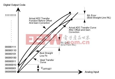
Latency/Pipeline Delay
Latency is the delay, measured in multiples of the ADC clock cycle, between the time the input signal is sampled and when the code word representing the sampled input signal value is acknowledged to be a valid digital code word at the ADC output.Major Code Transition
This term defines the midscale point where the MSB changes from low to high and all other bits change from high to low, and vice versa. This point is ideal for glitch-energy (see also Glitch Energy) measurements in a DAC, as the strongest switching noise occurs here.Monotonicity
Monotonicity is given when an ADC provides output codes that do not decrease/increase for a uniformly increasing/decreasing input signal, disregarding random noise (see also Random Noise).MTIMD
See Multi-Tone Intermodulation Distortion (MTIMD).Multi-Tone Intermodulation Distortion (MTIMD)
Multi-tone IMD is the ratio (in dB) of either input tone to the worst 3rd-order (or higher) intermodulation products. The individual input-tone levels are at -6.5dB FS or -7dB FS, and their multi-tone envelope is at -0.5dB FS.Multi-tone IMD usually defines up to four input tones.
Noise
The term "noise" is rather ambiguous if not qualified as to type. In general, it includes the effects of nonlinearities (INL, DNL), random (see also Random Noise) and fixed-pattern effects, and sampling-time error. Total noise, for instance, is any deviation of the output signal from the input signal, excluding deviations caused by differential gain and phase errors or DC-level shifts. Notable examples of such effects, here defined as noise, include quantization error, harmonic and intermodulation distortion, and spurious distortion (see also Quantization Error/Noise, Two-Tone Intermodulation Distortion, Multi-Tone Intermodulation Distortion, and Total Harmonic Distortion).Noise-Power Ratio (NPR)
NPR is a figure of merit that specifies the spectral power of contributed errors such as IMD and THD in a small-frequency band within the baseband of the composite input signal being processed and analyzed. Note: To measure NPR, random noise whose spectrum is approximately uniform up to a predetermined cutoff frequency less than half the sampling frequency must be generated. A notch filter then removes a narrow band of frequencies from the noise. To improve the measurement, the notch depth is recommended to be at least 10dB to 15dB greater than the NPR value being measured. Compared to the overall noise bandwidth, the notch width should be narrow. With this notched noise applied to the ADC input, one computes the frequency spectrum of the resulting code sequence and then calculates NPR as the ratio (in dB) of the average power spectral density inside the notched frequency band to that outside of it.NPR
See Noise-Power Ratio (NPR).Nyquist Frequency
Nyquist frequency is the maximum frequency that can be applied to an ADC's input with no aliasing effects (see also Aliasing/Anti-Aliasing). The Nyquist frequency is defined as:fSAMPLE ≥ 2 × fIN
Oversampling
Oversampling occurs when the input waveform of an ADC is sampled at a much higher frequency (fSAMPLE>2 × fIN) than the Nyquist (see also Nyquist Frequency) theorem mandates. This technique provides a processing gain by effectively reducing the noise floor of the converter. Doubling the sampling frequency increases the signal-to-noise ratio by 3dB.Overvoltage Recovery Time
Overvoltage recovery time is the amount of time required for an ADC to return to its specified characteristics after the end of a common-mode out-of-range or input-voltage out-of-range pulse. This term is commonly specified for a particular overvoltage level (for example, 1.5 × VREF).Pipeline Architecture
Also known as subranging quantizers, pipeline ADCs incorporate a number of consecutive stages, each containing a track/hold (T/H) amplifier, a combination of low-resolution ADCs and DACs, and a summing circuit that includes an interstage amplifier to provide gain. Additionally, digital error correction logic helps to avoid overlapping errors between the stages.Quantization
Quantization is a process whereby the continuous range of values of an input signal is divided into nonoverlapping subranges. Each of these subranges has a discrete value of the output uniquely assigned. Once a signal value falls within a given subrange, the output provides the corresponding discrete value.Quantization Error/Noise
This error is caused by the conversion of a signal with a continuous range of values to a digitized form that has only discrete values (analog-to-digital conversion). Quantization error or noise is defined as the difference between the original analog value and its corresponding, digitized output code.Random Noise
Random noise represents a nondeterministic fluctuation in the output of an ADC, described by its frequency spectrum and its amplitude statistical properties.SFDR
See Spurious-Free Dynamic Range (SFDR).Signal-to-Noise and Distortion Ratio (SINAD)
SINAD is computed by taking the ratio (in dB) of the signal power to the power of all spectral components minus the fundamental and the DC offset.Signal-to-Noise Ratio (SNR)
For a waveform perfectly reconstructed from digital samples, the theoretical maximum SNR is the ratio (in dB) of the full-scale analog input rms value to the rms quantization (or residual) error. The ideal, theoretical, minimum analog-to-digital noise is caused by quantization error only and results directly from the ADC's resolution (N bits):SNR(MAX) = (6.02 × N + 1.76)dBIn reality, there are other noise sources besides quantization noise, such as thermal noise, reference noise, and clock jitter. SNR is computed by taking the ratio of the rms signal to the rms noise, which includes all spectral components minus the fundamental, the first four harmonics, and the DC offset.
SINAD
See Signal-to-Noise and Distortion Ratio (SINAD).Small-Signal Input Bandwidth (SSBW)
A small analog input signal (for example, -20dB FS) is applied to an ADC in such a way that the signal's slew rate will not limit the ADC's performance. The input frequency is then swept up to the point where the amplitude of the digitized conversion result has decreased by -3dB. Note that the track/hold (T/H) input amplifier performance is usually the limiting factor for the small-signal input bandwidth.SNR
See Signal-to-Noise Ratio (SNR).Spectral Leakage
Spectral leakage is the result of an assumption in the FFT algorithm that the time record is precisely repeated throughout all time and that all signals contained in this time record are periodic at intervals corresponding to the length of the time record. However, a nonintegral number of cycles in the time record (fIN/fSAMPLE ≠ NWINDOW/NRECORD) violates this condition and causes spectral leakage. Only two cases can guarantee the acquisition of an integral number of cycles:- Synchronous sampling with respect to the input tone (see also Coherent Sampling)
- The capture of a transient signal that fits entirely into the time record
Spurious-Free Dynamic Range (SFDR)
SFDR is the ratio expressed (in dB or dBc) of the rms amplitude of the fundamental (maximum signal component) to the rms value of the next-largest spurious component, excluding DC offset.SSBW
See Small-Signal Input Bandwidth (SSBW).THD
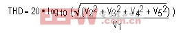
See Total Harmonic Distortion (THD).Total Harmonic Distortion (THD)
THD is typically the ratio (in dB or dBc) of the rms sum of the first four harmonics of the input signal to the fundamental itself. This is expressed as:where V1 is the fundamental amplitude, and V2 through V5 are the amplitudes of the 2nd- through 5th-order harmonics.
TTIMD
See Two-Tone Intermodulation Distortion (TTIMD).Two-Tone Intermodulation Distortion (TTIMD)
Two-tone IMD is the ratio (in dB) of either input tone to the worst 3rd-order (or higher) intermodulation products. Common input-tone amplitudes for the individual input frequencies are at -6.5dB FS or -7dB FS, and their envelope is usually -0.5dB FS.The IMD amplitudes for a two-tone input signal are found at the specified sum and difference frequencies:
fIMF_SUM = |m × fIN1 + n × fIN2|where m and n are positive integers. The condition that m and n are greater than zero creates the 2nd-order (fIN1+fIN2 and fIN1-fIN2) and 3rd-order (2fIN1+fIN2, 2fIN1-fIN2, fIN1+2fIN2 and fIN1-2fIN2, 3fIN1 and 3fIN2) intermodulation products.
fIMF_DIFF = |m × fIN1 - n × fIN2|
Undersampling
Undersampling occurs when the sampling rate of an ADC is much lower (fSAMPLE2 × fIN) than the applied input frequency, usually resulting in a loss of signal information, thereby causing aliasing (see also Aliasing/Anti-Aliasing). With proper filtering and an adequate input tone and clock frequency selection, the aliased components that contain the signal information can be shifted from a higher-frequency band to a lower-frequency band and converted.VCM
See Common-Mode Input Voltage (VCM).VDIFF
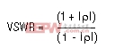
See Differential Input Signal (VDIFF).Voltage Standing-Wave Ratio (VSWR)
VSWR is the ratio of mismatch between the actual impedance and the desired or expected impedance. VSWR is related directly to the reflection coefficient ρ of a simple terminating impedance ZT.ZT depicts the ADC input termination impedance, and ZO represents the transmission-line impedance (nominally 50Ω).
ρ = (ZT - ZO)/(ZT + ZO)


評論