SSL2101設(shè)計(jì)的12W調(diào)光LED驅(qū)動方案
本文介紹了SSL2101主要特性,方框圖,典型應(yīng)用電路圖以及12W調(diào)光LED驅(qū)動器電路,輸入電壓230VAC和120VAC所用的材料清單(BOM).
SSL2101是NXP公司的開關(guān)電源(SMPS)控制器,可直接從火線整流電壓工作,并集成了相位調(diào)光器.器件包括高壓功率開關(guān),以及允許直接從整流的火線電壓工作的電路和給相位調(diào)光器供電的高壓電路.主要用于高達(dá)15W的LED模塊驅(qū)動.
SSL2101主要特性:
Easy migration to existing lighting control infrastructure, TRIAC and transistor dimmers
Supports majority of available dimming solutions
Valley switching efficiency is optimized by built-in dedicated circuitry
Built-in demagnetization detection
The IC has built-in OverTemperature Protection (OTP)
Short-Winding Protection (SWP) and OverCurrent Protection (OCP)
The IC has internal VCC generation that allows start-up from rectified mains voltage
Natural dimming curve by logarithmic correction
SSL2101應(yīng)用:
The SSL2101 is suitable for different power requirements, these include:
SSL, retro-fit lamps, e.g. GU10, up to a maximum of 10 W
LED modules, separate power supplies, e.g. LED spots, down-lights, up to a maximum of 15 W
LED strings, e.g. retail display, up to a maximum of 15 W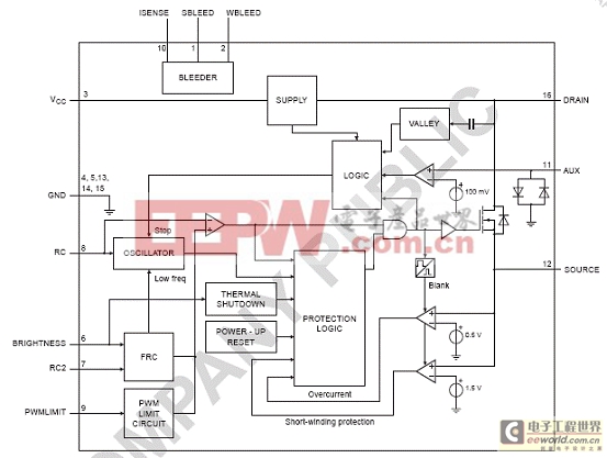
圖1.SSL2101方框圖
圖2.SSL2101反激應(yīng)用配置框圖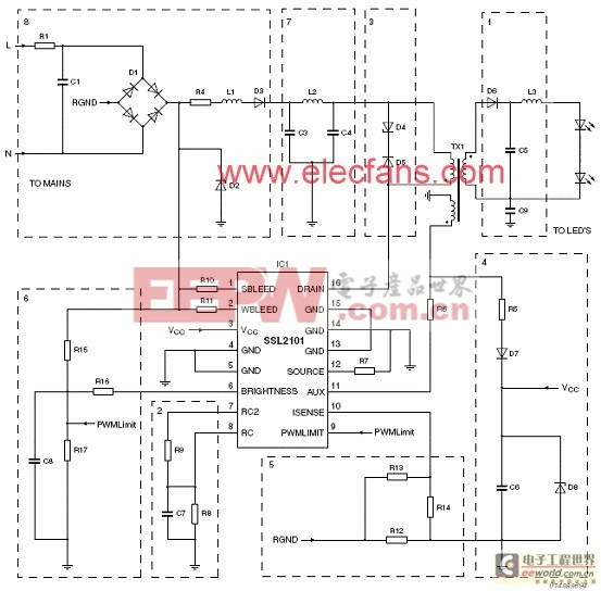
圖3.SSL2101典型的反激應(yīng)用電路圖
圖4.SSL2101典型的反激應(yīng)用和元件電路圖
SSL2101/2102 12W調(diào)光LED驅(qū)動器
The SSL2101/2102 12 W LED driver is a solution for a professional application with multiple high power LEDs that requires galvanic isolation and a safe output voltage. It is mains dimmable for both forward phase (TRIAC) dimmers, and reverse phase (Transistor)dimmers. It can generate up to 16 W output power, which is equal to a 100 W incandescent lamp (at 63 Lumen/W). Examples are shelf lighting, down lighting, LED lighting for bathrooms etc.The design gives an example of how to make a drive that is suitable for small form factor applications like retrofit lamps.
The board needs to be connected to mains voltage. Touching the reference board during operation must be avoided at all times. An isolated housing is obligatory when used in uncontrolled, non laboratory environments. Even though the secondary circuit with LED connection has a galvanic isolation, this isolation is not according to any regulated norm. Galvanic isolation of the mains phase using a variable transformer is always recommended.
The board can be optimized for a 230 V (AC) (50 Hz) or for a 120 V (AC) (60 Hz) mains source. Besides the mains voltage optimization, the board is designed to work with multiple high power LEDs with a total working voltage of between 9 V and 23 V.
The output current can be limited using trimmer R20. On request, a dedicated LED load can be delivered that is to be connected to K3. Connector K2 can be used to attach other LED loads. The output voltage is limited to 25 V. When attaching a LED load to an operational board (hot plugging) an inrush peak current will occur due to discharge of capacitor C6.After frequent discharges, the LEDs may deteriorate or become damaged.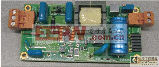
圖4.12W調(diào)光LED驅(qū)動器外形圖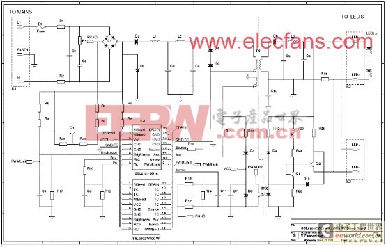
圖5.12W調(diào)光LED驅(qū)動器電路圖
材料清單(BOM)(230VAC):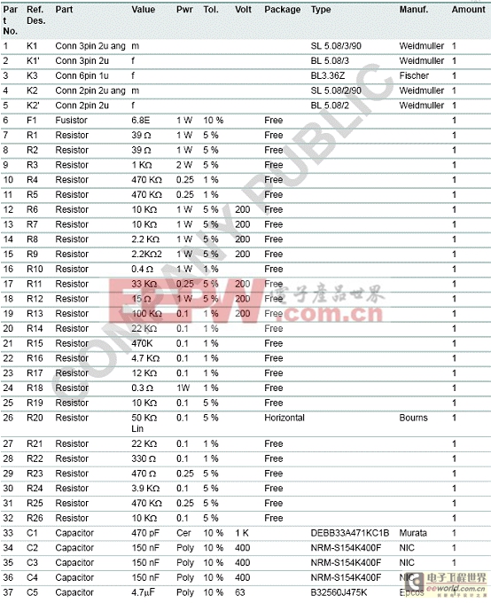
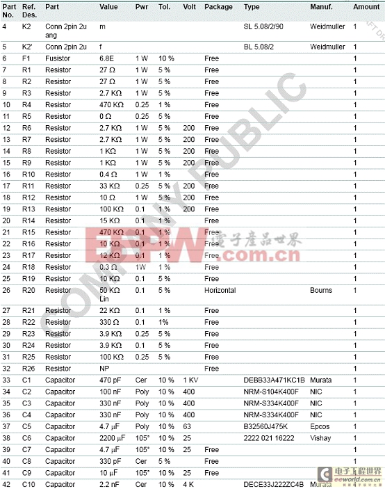
材料清單(BOM)(120VAC):


評論