音頻鑒定報告的DS1802雙數(shù)字音頻電位-Audio Cha

Purpose
The purpose of this document is to provide an examination of the DS1802 Dual Digital Potentiometer's audio characteristics. Test circuits were developed with the goal of measuring absolute error between tap points, inter-channel matching or tracking between the two potentiometer wipers, total harmonic distortion (THD), intermodulation distortion (IMD), and cross-talk. Additionally, data is provided for mute levels for each potentiometer, as well as active and standby current as a function of temperature and voltage. For this report, tests are restricted to the range of frequencies 20Hz to 20kHz.Test Circuit Configuration
To evaluate the DS1802's audio performance, the circuit of Figure 1 was constructed. As shown, this circuit consists of two NE5532 Op Amps connected in a non-inverting unity gain configuration. Inputs to these buffer stages were taken from each wiper of the DS1802.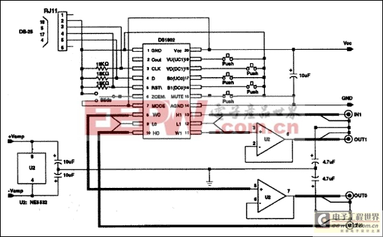
Figure 1. Test configuration circuite.
Several steps were taken to minimize the effects of extraneous noise on measurement data. Shielded cabling was used on all inputs and outputs from (or to) the DS1802 and NE5532 Op Amps. All ground signals were tied to a common point and power supplies were capacitively coupled to ground using 10 μF capacitors. Additionally, both the DS1802 and NE5532 Op Amps used separate power supplies.
Once assembled, this circuit was mounted inside a metal testbox to provide additional protection against coupling of random noise from external sources such as computer monitors, lights, etc. BNC connectors were used for inputs and outputs to test equipment.
Test Measurement Equipment
Audio measurements were performed using the Audio Precision-System One A version audio analyzer under PC-control. This test equipment provided the means of measuring THD+N, IMD, cross-talk, absolute error, and inter-channel matching.Test Measurements Performed
As stated in the scope of this document, device tests were completed on absolute error between tap points, inter-channel matching, THD+N, IMD, cross-talk, mute-levels, and device current characteristics as a function of temperature. These tests and data are presented in the following pages of this section of the report.Absolute Error and Summary
Absolute error is defined as the difference between the expected voltage output and the measured voltage output at a given wiper position. The DS1802 is specified to provide an absolute tolerance of ± 0.5 dB for any given wiper position. For example, wiper position 48 would be expected to provide -48 dB ± 0.5 dB of signal attenuation difference relative to wiper position 0 (or the input signal if connected to the high-end terminal of the potentiometer).Graphical data is presented in Figures 2 and 3 for a sample set consisting of five units of the DS1802. Figure 2 presents actual data for the five devices tested. Figure 3 further summarizes this data by presentation of the calculated average. The absolute error data taken in these tests indicate the DS1802 performs well within specified data sheet limits of ± 0.5 dB.
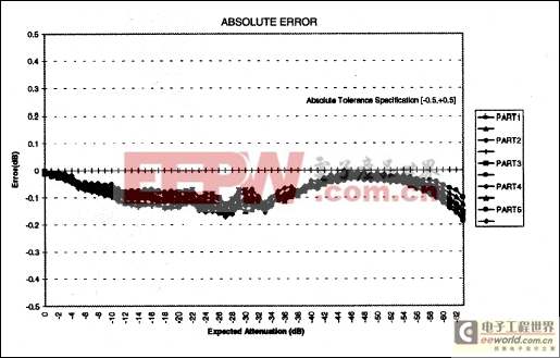
Figure 2. DS1802 Absolute error.
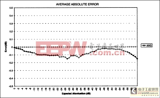
Figure 3. DS1802 Average absolute error.
Inter-Channel Matching
The DS1802 has two potentiometers per device. Inter-channel matching provides a way to measure how closely the wiper positions of each potentiometer match. Inter-channel matching is defined as the difference between the same wiper positions of potentiometer 0 and potentiometer 1. For example, wiper position 15 of potentiometer 0 and potentiometer 1 should differ by no more than ± 0.25 dB by specification of the DS1802.Figure 4 provides actual data taken on the units, while Figure 5 shows a summary of the average data. Average data for inter-channel matching indicates that this device characteristic falls within a ± 0.05 dB window; which is well within the data sheet specification of ± 0.25 dB.
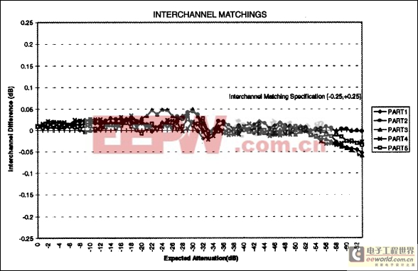
Figure 4. Inter-channel matching.
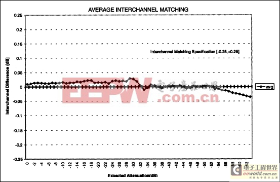
Figure 5. Inter-channel matching summary.
Total Harmonic Distortion + Noise (THD+N) vs. Frequency
Total Harmonic Distortion + Noise as a function of frequency is presented in Figures 6, 7, and 8. Figure 6 presents data for a 80kHz bandlimited signal having no additional filtering. The data presented in Figure 7 is bandlimited to 30kHz and includes data filtered using the A-weighting filter. Figure 8 provides data for an input signal bandlimited to 22kHz and corresponding data when filtered using the A-weighting filter. Device and system configuration for this data is taken with the supply voltage of the DS1802 equal to 5 volts, a 1 Vrms input signal, and the wipers of potentiometer 0 and potentiometer 1 set to position 6 (6 dB of attenuation).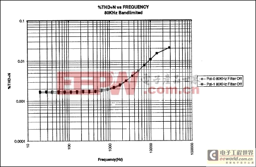
Figure 6. %THD+N vs. Frequency 80kHz bandlimited.
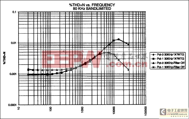
Figure 7. %THD+N vs. Frequency 30kHz bandlimited.
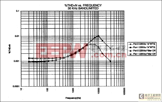
Figure 8. %THD+N vs. Frequency 22kHz bandlimited.
By setting the wiper position of the potentiometer at some level other than position-0 allows the potential user of the DS1802 to view distortion of the part as the input signal covers some portion of the resistor array. A position setting of 0 primarily allows the examination of the input signal source. The position-6 setting used in these tests provides a worst case selection for monitoring %THD+N.
The DS1802 is specified for a %THD+N of 0.002% at 1kHz. This specification is derived using the 80kHz bandlimited input signal at 1Vrms, and a position-6 potentiometer setting. Across the 20Hz to 20kHz frequency range %THD+ N is less than 0.02% maximum with the 80kHz bandlimited signal. Additionally, %THD+N across the 20Hz to 20kHz frequency range is significantly improved using bandlimited signals in conjunction with the A-weighting filter.
The A-weighting filter is a specific noise weighting filter ( ANSI S1.4, IEC Recommendation 179) used to produce noise measurements which correspond well with human observations over the audio frequency range.1 More detailed information concerning this filter can be found in the ANSI specification stated above or in the Audio Measurement Handbook published by Audio Precision, Incorporated.
Intermodulation Distortion (IMD)
Intermodulation distortion data is provided for the SMPTE and the CCIF intermodulation measurement standards. Data is presented as a function of amplitude for each measurement technique and is shown in Figures 9 (for SMPTE) and 10 (for CCIF).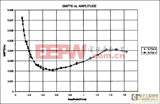
Figure 9. SMPTE Intermodulation distortion vs. amplitude.
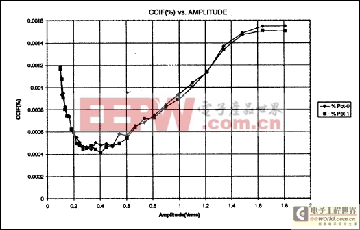
Figure 10. CCIF Intermodulation distortion vs. amplitude.
The SMPTE (Society of Motion Picture and Television Engineers) standard specifies a two-sinewave test signal consisting of a low-frequency, high-amplitude tone linearly combined with a high-frequency sinewave at 1/4 the amplitude of the low-frequency tone. The SMPTE specification calls for 60Hz and 7kHz as the two sinewaves. When a non-linear device is subjected to a two-tone test signal, intermodulation products appear as sidebands around the high-frequency tone. The percentage intermodulation distortion is defined as the percentage of amplitude modulation, represented by the second and third order pair of sidebands, of the high-frequency signal. Second order sidebands around the high frequency tone are spaced at a frequency equal to the low-frequency tone (FH ± FL). Third order sidebands are spaced at twice the low-frequency tone or FH ± 2FL. (FH and FL correspond to the highfrequency and low-frequency tones, respectively.2)
CCIF intermodulation distortion testing consists of using two equal-amplitude, high-frequency signals


評論