RT9173B應用電路及參數(shù)資料

The regulator is designed to convert voltage supplies ranging from 1.7V to 6V into a desired output voltage of which adjusted by two external voltage divider resistors. The regulator is capable of sourcing or sinking up to 2A of current while regulating an output voltage to within 40mV.
The RT9173B, used in conjunction with series termination resistors, provides an excellent voltage source for active termination schemes of high speed transmission lines as those seen in high speed memory buses and distributed backplane designs. The voltage output of the regulator can be used as a termination voltage for DDR SDRAM.
Current limits in both sourcing and sinking mode, plus on-chip thermal shutdown make the circuit tolerant of the output fault conditions.
The RT9173B are available in the popular 5-lead TO-252 and fused SOP-8 (the multiple VCNTL pins on the SOP-8 package are internally connected but lowest thermal resistance) surface mount packages.
Features
? Support Both DDR I (1.25VTT) and DDR II (0.9VTT) Requirements
? SOP-8 and TO-252-5 Packages
? Capable of Sourcing and Sinking Current
? Current-limiting Protection
? Thermal Protection
? Integrated Power MOSFETs
? Generates Termination Voltages for SSTL-2
? High Accuracy Output Voltage at Full-Load
? Adjustable VOUT by External Resistors
? Minimum External Components
? Shutdown for Standby or Suspend Mode Operation with High-impedance Output
? RoHS Compliant and 100% Lead (Pb)-Free
Application
? DDR Memory Termination Supply
? Active Termination Buses
? Desktop PC/AGP Graphics
? Set Top Box/IPC
? Supply Splitter
Typical Applications Circuit
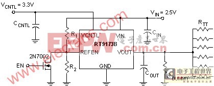
R1 = R2 = 100kW, RTT = 50W / 33W / 25W
COUT(MIN) = 10mF (Ceramic) + 1000mF under the worst case testing condition
RDUMMY = 1kW as for VOUT discharge when VIN is not present but VCNTL is present
CIN = 470mF (Low ESR), CCNTL = 47mF


評論