使用寬帶電壓和電流反饋運算放大器時的應用基礎

(Click to Enlarge Image)
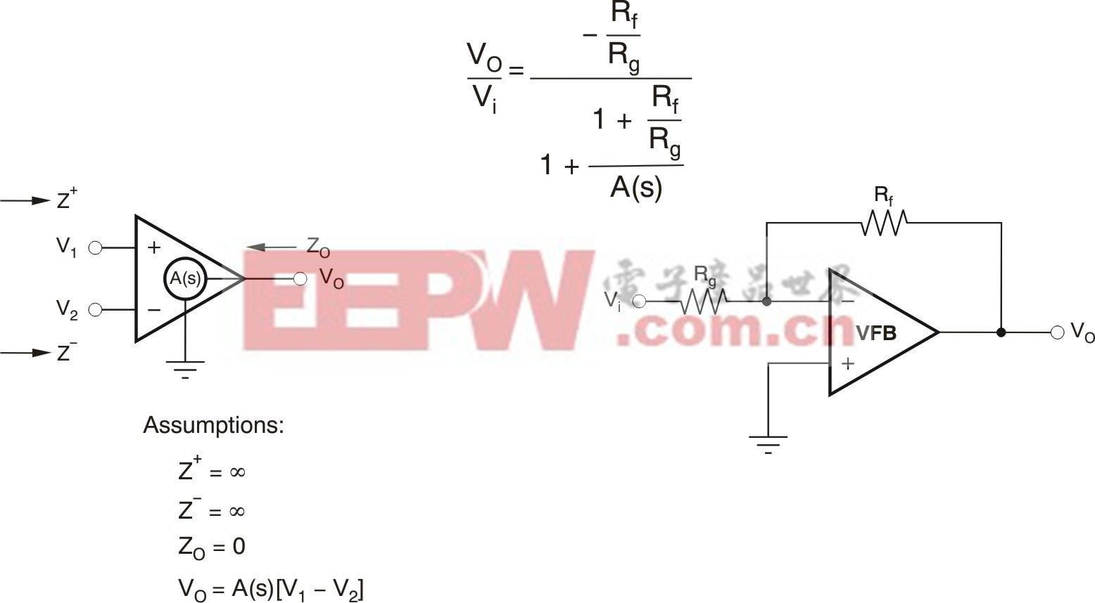
Figure 1. Open loop to closed loop conversion for voltage feedback.
The transfer function has the desired gain in the numerator (-RF/RG) and a loop gain (LG) term in the denominator that determines the frequency response. One way to understand this LG is to plot [20 · Log (A(s))] and [20 · Log(1+RF/RG)] on the same grid. The key issues for this plot are: 1) the separation between these two curves at lower frequencies (this separation shows the magnitude of the loop gain); and 2) at what frequency they intersect.
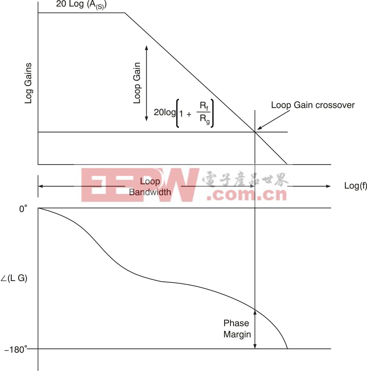
At the point of intersection, sometimes called loop gain crossover, the term in the denominator of the transfer function drops to 1 + 1e-jθ(where jθ is the angle of that expression). The important check is that this angle is well away from -180 degrees to avoid closed loop oscillations or peaking.Figure 2shows an example loop-gain plot of these two terms, where a simple single-pole response for A(s) is assumed and no phase added by the feedback network.
(Click to Enlarge Image)
Figure 2. Loop gain and phase for a VFB op amp. X-axis is log frequency.
In Figure 2, the (1 + RF/RG) term is assumed to add no phase impact to the loop gain; only the open-loop phase of A(s) introduces loop phase shift in this simple example. This graph is the lower plot, where the loop gain crossover frequency is mapped down to find the remaining phase margin at that frequency.
Note that it is impossible for the VFB to change the signal gain without changing the loop-gain characteristic. This effect is where the gain bandwidth product (GBP) concept arises. If the gain increases, the bandwidth must decrease. If the gain decreases, the bandwidth increases, and the phase margin will normally decrease. (SeeReference 1for a more complete discussion.)
In contrast, the internal workings of a CFB op amp are quite different. Those blocks and the resulting closed loop transfer function for the inverting configuration are shown inFigure 3where, again, an inverting configuration is used and a single pole internal transimpedance gain is assumed for Z(s).

(Click to Enlarge Image)
Figure 3. Current feedback internal structure and closed loop response.


評論