隔離式電源電信應(yīng)用-Isolated Power Suppl
A number of the elements involved in noise generation are not predictable by analysis. Only when the power supply has been implemented physically can you perform the analysis and experimental tests that enable design of the EMI filter. To allow a reasonable spread of component values during production, this filter should have approximately 10dB margins on the specification limits.
Introducing a capacitor between primary and secondary provides a low-impedance path for high frequencies. This capacitor (usually a ceramic type with a value of 1nF to 4.7nF or so) forces noise to flow through the converter internally, thereby lowering the noise on both sides of the power supply by several decibels. Radiated noise is generally suppressed by placing the complete converter with an EMI filter in a six-sided metallic box.
Safety
For secondary outputs to be defined as telecom extra-low voltage (TELV), they must be isolated from the input side of the converter. TELV outputs can be touched by an operator without any particular attention or protection. For this purpose, the international specifications EN60950 and UL950 define minimum isolation voltages between input and output, and minimum-allowed distances between primary and secondary parts of the converters. Refer to Tables 3 and 4 (in EN60950).As shown in these tables, the minimum-allowed creepage and clearance distances1 depend on the construction technology, the working environment, and the operating voltage. As an example, for an input voltage of 76VDC, a pollution degree2 of 3, and reinforced insulation, the creepage and clearance distances are 2mm and 4mm, respectively.
You can easily implement a safety area on the printed circuit board in which the only component between primary and secondary sections is the power transformer. This transformer must incorporate the safety distances required by international specifications (enameled copper cannot be defined as insulation).
Four main technologies are available for meeting the safety-insulation requirements in transformer construction, each with its own advantages and disadvantages. Each of these approaches is examined below, with respect to a four-winding transformer in which the primary winding is split in two parts: _-Primary/Secondary/Auxiliary-secondary/_-Primary.
1. One approach provides insulation by sleeving the beginning and the end of each winding (Figure 8). Windings are placed 2mm from the border of the coil former. Total creepage distance between two windings is 2mm+2mm = 4mm. (Only 2mm are necessary, but the additional 2mm margin can improve yields and manufacturing time during production.) Because enameled copper is not considered insulation, the ends of each winding must be protected by an insulating material; otherwise, the creepage distance is reduced to less than 2mm.
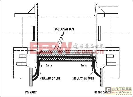
Figure 8. The insulation in this cross section of a wound transformer consists of sleeving and insulating tape. Because sleeves are defined as insulation, this approach lets you reduce the safety distances by a factor of two.
Additional insulating material is required between the primary and the secondary windings. If reinforced or double insulation is needed, there must be at least two layers of insulation. Because it allows good coupling between windings, this production technology minimizes leakage inductance and is useful in constructing transformers with multiple secondary outputs. It also allows a good compromise on delivered watts per unit volume of transformer. Because protection sleeves cannot be placed automatically, the manual work required makes this technique quite expensive.
2. Another method entails providing insulation by placing the primary windings close to one side of the coil former and the secondary windings on the other side (Figure 9). Distance is kept at 4mm, but coupling between windings is very poor. This approach is almost impossible for small transformers.
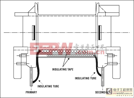
Figure 9. This is a cross section of a wound transformer, in which the insulation is provided by insulating tape (enameled copper is not defined as insulation). Safety regulations mandate the minimum distances between windings.
3. The use of special wire for the secondary winding, covered by two layers of insulating material (recognized by UL as double insulation), can be a solution for small-geometry transformers. This approach can be automated up to 100%. On the other hand, the high cost of the wire required makes it less attractive.
4. A coil former consisting of two concentric half sections in which all the primaries are contained in one section and all the secondary windings in the other allows efficient assembly of the transformer. The two concentric parts are first wound separately (primary windings in one, secondary windings in the other) and then joined in a second operation. This process can be automated completely. It reduces manual re-work almost to zero and yields the least expensive transformer of its type available today. Coupling between primary and secondary is poor, however, and (unfortunately) the split-primary transformer under examination cannot be built this way. This approach is of great interest for low-power transformers in flyback topologies that operate from the 120VAC mains (a cellular-phone battery charger, for example).
Minimizing mechanical dimensions is a common requirement for telecom converters in PC-board applications. Because safety specifications define a minimal creepage distance related to the pollution degree of the external environment, you can improve the pollution degree and reduce creepage distance by placing the transformer in a box filled with resin, under vacuum. By modifying the transformer's internal environment this way, a pollution degree of 1 is easily achievable (refer to Table 4).
Transient-Voltage Protection
Virtually all electrical equipment is subject to excessive voltage pulses during normal operation. Such pulses can be generated by lightning or by nearby electrical equipment such as large electrical motors. International specifications EN61000-4-5 and EN41003 define the pulse types that certified equipment must be able to withstand.In telecom power supplies operating from rectified voltage, a 1.5kW transient-voltage suppressor (TVS) is generally sufficient to protect the supply and meet all the international specifications necessary for CE approval. More complex is the protection of an RS232 or RS485 interface used for maintenance and communications inside the end equipment. It can be expensive to place a TVS on each line, especially if the lines must maintain low parasitic capacitance to support high transmission data rates.
A wide choice of RS-232 and RS-485 interface ICs for this purpose are available from Maxim. All include ESD protection tested per IEC1000 specifications at levels up to ±15kV. That spec ensures an interface compliant with the CE requirements, without need for further tests in production.
Output Overcurrent and Overvoltage Protection
Output protection prevents damage to the power supply as a consequence of load currents ranging from zero to that of a short-circuited output, as well as damage to the load as a result of irregular supply voltage caused by such faults. The following is an examination of two circuits: one to protect the power supply from unusual load currents and the other to protect the load from unusual output voltages.Telecom power supplies require a constant output-current characteristic. When load current exceeds a certain level, generally 20% to 40% above the nominal value (Inom), the converter output becomes a constant-current generator. For that condition, reducing load resistance only lowers the output voltage.
In terms of power management, the worst-case condition for such telecom supplies is the worst-case maximum load current (Inom plus 40%), which occurs when the output voltage is still regulated. Delivered power is 40% above nominal and can persist indefinitely. The entire power supply must be capable of withstanding this level of output power. Because the necessary over specification can affect mechanical dimensions and price of the heatsink, a system can benefit by restricting the allowed tolerance on output current. Maxim offers a wide choice of high-side precision current monitors for this purpose, ranging from the simple MAX4173 in a SOT23 package (Figure 10) to the MAX471, which can also detect the current flow direction.
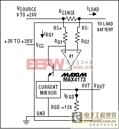
Figure 10. In high-side current measurements, the MAX4173 provides a voltage referred to ground and proportional to current flowing in the sense resistor.
These ICs employ a resistor in series with the load current that drops only a few milliv


評論