隔離式電源電信應(yīng)用-Isolated Power Suppl

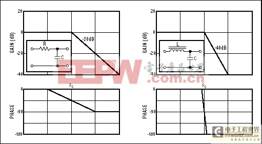
Figure 11. These Bode plots depict a single-pole RC network and a double-pole LC network.
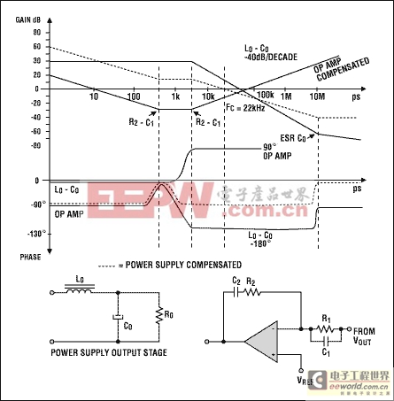
As an example, consider the compensation of a power supply operating at 70kHz with a duty cycle of 50%, described by the power-supply characteristic of Figure 12. The maximum corner frequency is fSWITCHING/(2x3.14xD) = 22kHz. Beyond this corner frequency, the output capacitor, the inductor, and the load resistor produce a -40dB/decade attenuation and a 180° phase shift. The op amp's bandwidth is more than 10MHz, but its associated RC components introduce a pole and zero, to compensate phase lag introduced by the LC pole and to provide at least 45° of phase margin at fC.

Figure 12. Simplified Bode plots depict a power-supply output and its compensation network.
To ensure good output-voltage regulation at DC, a pole in the error amplifier reduces the gain by -20dB/decade. A zero caused by R2-C2 modifies the gain slope to 0dB/decade, and R2-C1 causes a gain increase to +20dB/decade. As a result, phase introduced by the compensated op amp starts at -90° (due to the first pole), goes to 0° (due to R2-C2), and rises to +90° (due to R2-C1). Summing the output-LC and compensated-op-amp characteristics gives the overall result (dotted line), which indicates a power supply compensated with fC = 22kHz and a phase margin of 90°.
________________________
1Per the American UL Standard (also adopted by the European EN60950 Standard), clearance is the minimum-allowed distance specified for separation of uninsulated conductive surfaces of opposite polarity. Creepage is a corresponding distance between two such surfaces, measured along any connecting surfaces (rather than the line-of-sight through-air distance specified for clearance).
2Per the American UL Standard (also adopted by the European EN60950 Standard), pollution degree 2 environments can have nonconductive contaminants or temporary conductivity caused by condensation. Pollution degree 3 environments can have conductive contaminants.


評論