監(jiān)測集成電路監(jiān)控電池供電設(shè)備

DC-DC Boost Circuit Extends Shutdown Time
If a backup/shutdown routine requires more time than you can reasonably provide with storage capacitors, you can use a dc-dc converter to sustain VCC while the shutdown routine is in progress. The μP can then shut down the dc-dc converter once the backup is complete.In Figure 4, for example, IC2 is a step-up converter that provides 5V to the system and μP supervisor (IC3) when the main 5V supply fails. At the onset of such a power failure, as the main supply falls below 4.65V, IC1 turns off Q1, brings IC2 out of shutdown, and interrupts the μP. IC2 then boosts the supply voltage from 4.65V back to 5V. The reset threshold is not encountered, so a reset to the μP is not issued. When the μP finishes its shutdown routine, it simply pulls IC2 into shutdown again and the system goes into its normal battery-backup mode.
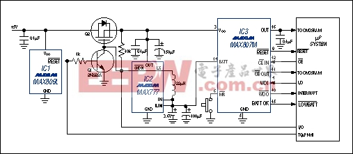
Figure 4. A threat of VCC loss causes the boost converter (IC3) to turn on and restore VCCto its nominal level.
The boost converter delivers up to 100mA while powered from a lithium cell that has been drained to 2.5V. If desired, you can provide separate batteries for the RAM backup and the boost converters.
Guarding Against False Resets
The supervisory circuit must not issue resets in response to system noise or VCC load transients. About 50mV of noise on the digital power-supply lines is common. Load transients, which occur when modules, peripherals, and other subsystems are turned on or off, can cause serious problems if the reset comparator's propagation delay is too short.You can avoid false resets by choosing a supervisory circuit whose reset comparator has a propagation delay of 10μs to 30μs. Shorter propagation delays (of a few hundred nanoseconds) react quickly to VCC transients, and are therefore likely to generate false resets. Long delays, on the other hand, can allow VCC to fall too far outside the system IC's operating range before the processor is reset. The majority of 5V applications include sufficient capacitance to reduce the VCC fall rate such that a reset occurs before VCC falls below the minimum level specified in the IC's electrical characteristics.
Battery Backup
For critical systems that require non-volatile memory, the designer can choose either erasable/programmable memory or a CMOS RAM with backup battery. EEPROMs and flash memory are rated not only for memory capacity, but also for the number of write cycles they can undergo. The most common non-volatile memory includes a switch that connects the CMOS RAM to the lithium backup battery or VCC, whichever is higher.Large capacitors (around 0.5F) offer a popular method for providing a short-duration memory backup. Called SuperCaps? or MaxCaps?, these capacitors charge from VCC through a diode during normal operation (Figure 5). Charging current is limited by the capacitors' internal series resistance, which is relatively high. The RAM is switched from VCC to the capacitor when VCC collapses below the IC's reset threshold. The available backup time depends on the level of quiescent current into the RAM and supervisor IC, and the self-discharge leakage of the capacitor itself. For the many systems that draw only tens of microamps in backup mode, such backup capacitors can maintain the memory contents for several hours. The 1μA quiescent currents of Maxim supervisors, for instance, are generally insignificant.
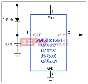
Figure 5. A very large capacitor (0.47F in this case) can serve as a backup battery in systems with low quiescent current.
Backup-battery switchover in 3V applications presents a challenge: How do you determine when to switch between a 3.3V VCC and a 3.6V lithium backup cell? One way is to define a ground-referenced voltage that is higher than the CMOS RAM's minimum standby voltage. Thus, VCC supplies the RAM until it falls to slightly more than 2V; RAM is then switched to the backup battery (Figure 6).
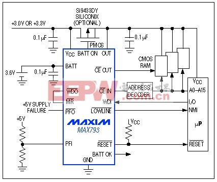
Figure 6. When VCC sinks to slightly above 2V, this system switches the CMOS RAM from VCC to the backup battery.
Special Cases
To conserve battery energy, designers of battery-operated portable equipment often make use of the 80CL51 μC's power-down mode. If the preservation of CMOS memory content is critical, IC1's active-low LOWLINE output (Figure 6) generates an interrupt. This interrupt signal can trigger a shutdown routine when the main battery voltage goes low enough to cause VCC to fall out of tolerance. RAM contents are kept alive by whatever energy remains in the battery.With the μC in power-down mode and the supervisor's RESET connected directly to the μC's RST terminal, a VCC decline below the reset threshold will cause RESET to go high. This, in turn, wakes up the μC and places it in run mode, increasing its quiescent current from approximately 100μA to 6mA. Battery voltage continues to fall and VCC remains below the threshold, so 6mA will drain the battery, considerably shortening the available backup time.
Simply combining active-low LOWLINE and RESET with an AND gate (Figure 7) ensures that IC3's RST is driven high only for the reset timeout period (not when VCC is falling). In other words, RST goes high after VCC has been restored (by recharging the battery or installing a fresh one) and has recrossed the low-line threshold. The AND gate thus allows the sleeping controller to remain in a sleep state.
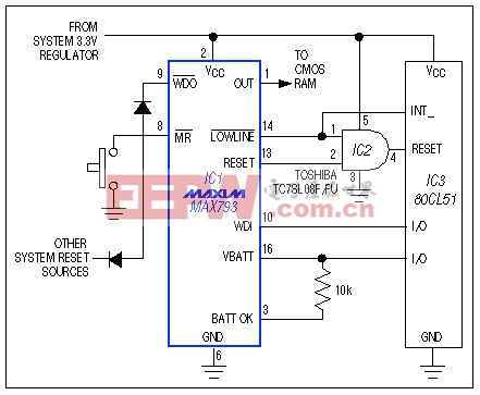
Figure 7. The AND gate preserves battery energy by preventing an unnecessary shift in microcontroller operation-from sleep mode to the higher-current idle mode.
With VCC in its normal operating range, RESET is low and active-low LOWLINE is high. When VCC falls below the low-line threshold (typically 45mV above the reset threshold), active-low LOWLINE goes low, signaling the 80CL51 to begin its shutdown routine. RESET asserts when VCC encounters the reset threshold, but active-low LOWLINE forces the AND-gate output to remain low.
On power-up active-low LOWLINE remains low, therefore RST remains low until VCC crosses the low-line threshold. RESET then propagates through to the RST terminal for the duration of the reset timeout period. As a result, the 80CL51 exits its sleep mode only when VCC is valid.
Also desirable in this application is an ability to detect whether the battery has discharged below the safe RAM-backup voltage at any time during the sleep period. Using this information, the system decides whether to perform a "warm boot" based on the contents of the RAM, or a "cold boot" that starts from scratch because low battery voltage may have corrupted the RAM data. IC1's BATT terminal (pin 16) tells the μC which boot is appropriate.
IC1 has a low-battery comparator that normally indicates the state of a backup battery connected to its BATT terminal. This comparator output (BATT OK) is not latched. The application of Figure 7 has no backup battery, so you can use BATT to latch the state of BATT OK. Simply connect BATT to an available I/O pin on the 80CL51, and to the BATT OK terminal via a 10kΩ resistor.
To set up for normal operation, the μC pulses the


評論